The first step in selecting the right product for your cooling system application is to determine the heat load, or the amount of heat generated by your system. This article explains how to establish heat load for any liquid cooling application. The same process can be adapted for air cooling systems as well.
Rough Estimate for Heat Load
A quick and dirty method of estimating heat load is to assume that all electrical energy entering a process is converted to heat. From the 1st Law of Thermodynamics we know that the amount of energy exiting a system can never be greater than the amount of energy entering a system. The heat load can be conservatively estimated to be equal to the amount of electricity consumed if electricity is the only form of energy entering a system.Formula for Specific Heat
To determine heat load more accurately, use the heat transfer equation: Q = m x Cp x ΔT where:- Q = heat load (W [BTU/hr])
- m = mass flow rate (kg/s [lb/hr])
- Cp = specific heat (J/g-K [BTU/lb °F])
- ΔT = change in temperature (°C [°F])
Test Setup for Calculating Heat Load
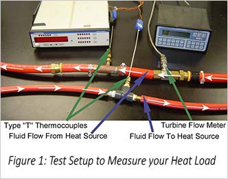
To determine Q using the above heat transfer equation, you will need to obtain the values m and ΔT experimentally. To measure these the temperature differential and mass flow rate values you will need the following equipment: Two (2x) Type “T” Thermocouples – Recommended accuracy: ± 0.2°F A Turbine Flow Meter – Recommended accuracy: ± 1% of Reading The thermocouples and flow meter can be used to measure fluid temperature change and flow rate of the cooling fluid when your system is at peak load operation (see Figure 1). Using the fluid’s specific heat (properties of commonly used fluids can be found in the Thermal Reference Guide in our Technical Library) and the above equation, heat load can be computed.
What Are Thermocouples?
Thermocouples are a sensor built from two dissimilar metals that generate an electrical charge based on the temperature at the joint between those two materials. Thermocouples are a crucial element in thermal testing.
Accurate measurements rely on placing the thermocouple junction as close to the point under test. If a material is in the way, thermal resistance and thickness can also help determine the temperature at a specific point but decrease the overall accuracy of your measurement.
Thermocouples Measurement Accuracy
The accuracy of the thermocouples and flow meter is particularly important, as a small decrease in accuracy can cause a significant error percentage. For example: if the temperature rise is 10 °C and the thermocouples are accurate to ± 0.5 °C, the temperature rise measurement could be off by as much as 1 °C, or 10%. This means that the overall heat load calculation cannot be more accurate than that ±10%. If the temperature rise is less than 10 °C, the ± 0.5 °C becomes an even higher error percentage. When the temperature error is given in °F or °C, the error percentage can be calculated by multiplying the thermocouple accuracy by two, then dividing by the change in temperature, and multiplying by one hundred.Thermocouple Calibration
We recommend calibrating the two thermocouples prior to recording measurements. If this isn’t possible, the accuracy of one thermocouple can be compared to the other. To do this, run a fluid stream through the thermocouples with no heat load. If the temperatures are the same, the exact temperature rise at peak operation can be used. Otherwise, account for the temperature difference of the two thermocouples under no heat load when conducting measurements at peak load operation. For thermocouples measuring different temperatures, subtract the temperature difference with no heat load from the temperature difference with heat load applied. For example: if the two thermocouples read 20.0 and 20.5°C when under no heat load, and 25.0 and 30.5°C with heat load applied, the change in temperature should be calculated to be (30.5 – 25.0) – (20.5 – 20.0), or 5.0°C.How to Measure Liquid Flow Rate Without a Flow Meter
If a flow meter is not available, measure the constant flow rate of the system with a graduated container and a timer. Collect the fluid in the graduated container over a measured period. Divide the amount of fluid by the amount of time that has elapsed. A constant flow rate is essential when measuring the flow in this manner. The density of the fluid should be used to convert the volumetric flow rate to mass flow rate.
These methods of determining heat load are generic to any liquid cooling application and can be used when sizing a CDU, recirculating chiller, cold plate, or heat exchanger.
Now I Know my Heat Load, What Next?
Once you’ve calculated the heat load of your system, you can start determining the amount of cooling you require. This piece of information combined with the amount of volume allowable for a cooling system will help thermal engineers select or develop a liquid cooling system that will meet your project needs.
Need help getting a pulse on your system? Contact our engineering team or learn more about our Testing Services.


